Analysis of D-Q Small-Signal Impedance of Grid-Tied Inverters
This paper unveils an interesting and important feature of three-phase grid-tied inverters - namely, that its q-q channel impedance behaves as a negative incremental resistor. An example shows that under weak grid conditions, a change of the PLL bandwidth could lead the inverter system to unstable conditions as a result of this behavior.
Abstract:
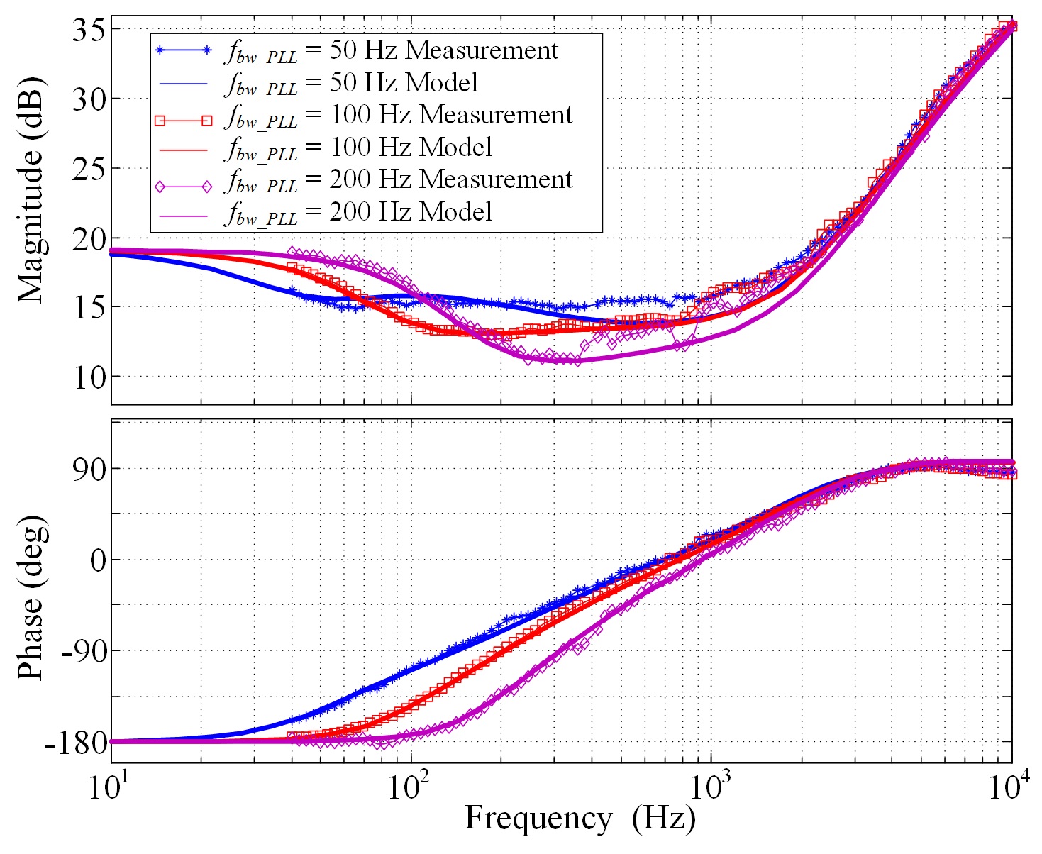
This paper analyzes the small-signal impedance of three-phase grid-tied inverters with feedback control and phase-locked loop (PLL) in the synchronous reference (d-q) frame. The result unveils an interesting and important feature of three-phase grid-tied inverters - namely, that its q-q channel impedance behaves as a negative incremental resistor. Moreover, this paper shows that this behavior is a consequence of grid synchronization, where the bandwidth of the PLL determines the frequency range of the resistor behavior, and the power rating of the inverter determines the magnitude of the resistor. Advanced PLL, current, and power control strategies do not change this feature. An example shows that under weak grid conditions, a change of the PLL bandwidth could lead the inverter system to unstable conditions as a result of this behavior. Harmonic resonance and instability issues can be analyzed using the proposed impedance model. Simulation and experimental measurements verify the analysis.

Citation
@article{wen2015,
  author = {Wen, Bo},
  title = {Analysis of {D-Q} {Small-Signal} {Impedance} of {Grid-Tied}
    {Inverters}},
  journal = {IEEE Transactions on Power Electronics},
  date = {2015-01-30},
  url = {https://ieeexplore.ieee.org/abstract/document/7027822},
  doi = {10.1109/TPEL.2015.2398192},
  langid = {en}
}