Model Levels – MOSFET and Inverters
MOSFET Model Levels
“Model level” is a concept that is very familiar to power electronics engineers when talking about power MOSFETs. In SIMPLIS which is a well-known power supply simulation package. It defines Level 0, 1, 2, and 3 models for power MOSFETs.
Level 0 models a switch with on/off resistance values, a body diode, gate resistance, and gate-to-source capacitance. The Level 0 model can be used in transient and AC analysis simulations.
Level 1 model adds an output capacitor parallel to the switch. Though it is a lumped linear capacitor, it enables the simulation of soft-switching circuits.
Level 2 model models a switch with forward transconductance gain, a body diode, and gate-to-source capacitance, plus nonlinear Gate-Drain, Drain-Source, and Gate-Source capacitors. It enables the simulation of switching losses, voltage and current stresses.
Inverter Model Levels
Modern power system design and analysis uses power flow or load flow simulation, dynamic simulation, and EMT simulation. For an inverter used in a PV or BESS system, different models are used for different simulations. Can we define Level 0, 1, and 2 models for an inverter in power system simulations?
Inverter Level 0 model – a model for power flow simulation. The inverter is set as a PQ node (real power P and the reactive power Q are fixed in magnitude) since it is controlled at its MPPT point with a constant power factor.
Inverter Level 1 model – a positive sequence phasor model or RMS model for transmission system dynamic simulation. This model describes the system dynamic only at fundamental frequency positive sequence. This kind of model cannot represent sub-line cycle information, so the sub-synchronous oscillation instability problem cannot be studied using such a model.
Inverter Level 2 model – an EMT (Electromagnetic Transient) model. This model represents the whole inverter by its full differential equations. Most power converter circuit simulations done by SIMPLIS, PLECS, PSim, and Matlab/Simulink are EMT model simulations.
| Power MOSFET in SIMPLIS | Inverter | |
|---|---|---|
| Level 0 | 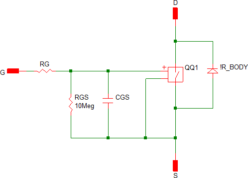 |
 |
| Level 1 | 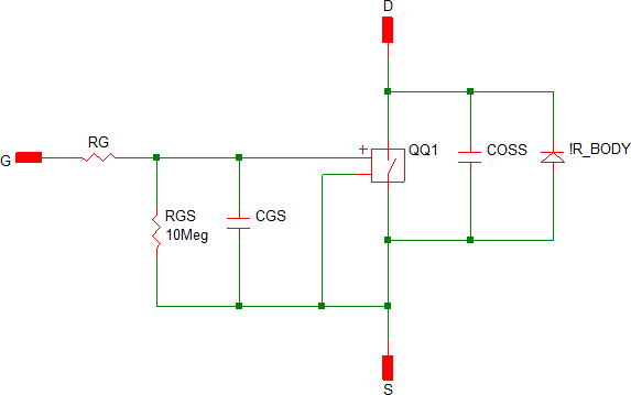 |
 |
| Level 2 | 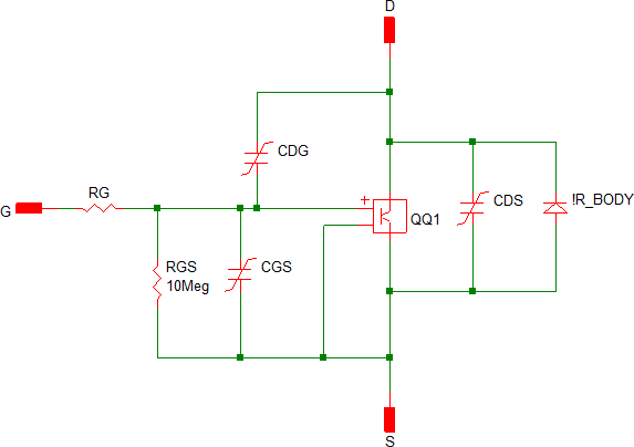 |
 |